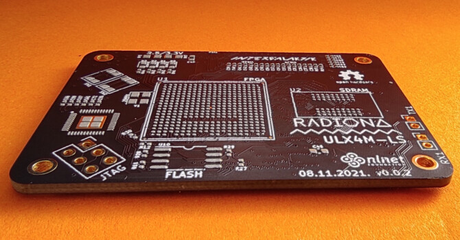
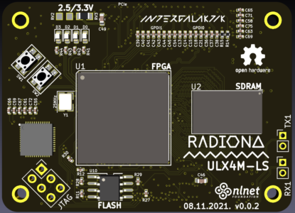
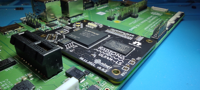
ULX4M-LS – NLnet funded FPGA board
At start of the year NLnet decided to sponsor development of modular FPGA, for now we will call it ULX4M as first version should have everything that ULX3S already has.
Goal is to make board modular and add more peripherals. We are specially interested in adding fast SerDes peripherals that are now missing on ULX3S. Along with that future plans are also to create modules with multiple FPGA vendors so we can do more vendor neutral coding.
https://nlnet.nl/project/ULX3S/
It all started with selecting connectors – you can check story here
http://lemilica.com/archives/3158
We ware also interested in blender so Paula joined team – her story is here
http://lemilica.com/archives/3141
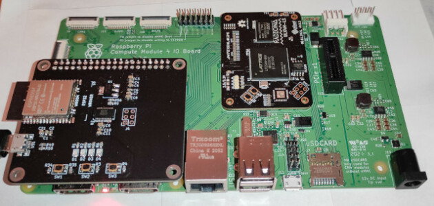
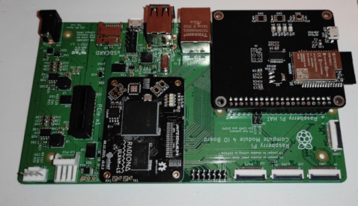
After we selected connectors and decided to go with CM4 IO compatible pin-out we have started to disassemble ULX3S and create new smaller modular board that will fit into CM4 IO carrier boards.
http://lemilica.com/archives/3204
But along with the work HW bugs arrived.
On ULX4M v001 we had two “big” issues, and few smaller ones that needed a fix…
First problem was that I did not know that a small board needs to provide 3.3V to a big board, so I did not connect 3.3V to the CM4 IO connector. On v001 this was fixed with a bit of wire, but that was first fixed on v002.
Second big problem was that the connectors did not fit perfectly in the slot.
On v002 I have moved connectors apart just a bit to get distance as described in the datasheet.
Next big thing but not issue was to get better routing to SDRAM.
Matching SDRAM lines is not not super important and it was working, but as we want a version with DDR3 this board is great first try to check how to do better routing.
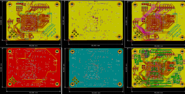
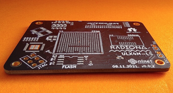
But before routing we needed to switch to a 6 layer board.
On the 4 layer board it was already visible that we cannot get a perfect ground plane below all lines.
So on v002 it was time to switch to a 6 layer board.
Switching to 6 layers was not so problematic.
I first deleted all ground polygons, then I selected power polygons and moved them off board.
After that in settings I selected the stackup I wanted.
I think about it and 3 signal layers should be sufficient for routing all pins.
For stackup I decided to go with Signal/GND/Signal/Power/GND/Signal
After I changed the layer count to 6 and named layers I checked if all signals are on the right layer.
As that was ok, I selected power polygons, switched them to power layer and moved them back on the board.
After that I created a new ground poligon on two ground layers.
Some more cleanup was still needed so I checked all layers again and moved all power lines to the power layer.
Next was to add buttons that were missing on v001.
I ordered a few types and selected ones that looked and felt good.
And now that we had everything set I could route SDRAM, and for that I first need to move it just a bit to the right – so I will have more room for length matching.
For checking all lines length I have used action plugins
https://github.com/MitjaNemec/Kicad_action_plugins
In kicad you first select Route-Tune Track Length, click on longest track and remember length.
After that use right click for options select – Length Tuning Settings – you can also press CTRL+L to set settings screen. On the Single Track Length Tuning screen set some length – it needs to be more or equal to the longest wire you want to tune, and that is why you need to write or remember the longest line length.
After setting parameters. Now you just click on any shorter line and just pull the cursor over it. You will get those fancy curved lines. You can use the keyboard: 1 2 3 4 for spacing and amplitude of line curves.
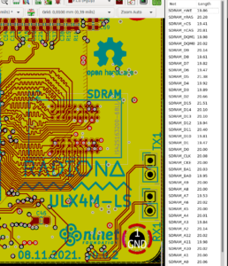
For SDRAM that should be enough, but for DDR3 we will probably need to take more things into account.
For example every chip package has some line from input pin to logic – those lengths when important are mostly in the datasheet. You also need to take into consideration every layer switching you are doing especially if you are going from top to bottom layer (or opposite) as that can add significant length.
And this is how routing looks now
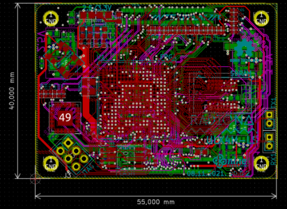
Connecting all GPIOs was also not so problematic on 6 layer boards, it is still not too crowded by signals.
I also needed to take HAT routing into consideration and that is bit tricky, as on ULX3S FPGA and ESP32 are sharing significant number of lines, and hat needs to access some lines that are not available on GPIO port, that goes for SDCARD and JTAG pins, as we want to use HAT for ULX4M programming, and we want to make sure that on HAT ESP32 is able to use SD CARD.
On v002 I also connected all MIPI DSI pins – on full port I have decided to put SerDes pins for experiments with v002. I also added 2.54mm pin holes on board that might be used as dipole antennas – so we can experiment if we can send/receive some data…
One big thing that is still a problem is ethernet – it is hard to decide what chip to put there as none of Gb chips are currently available :(
But in this version I have added a QFN48 footprint so maybe in the next version I will not need to order additional stencil.
In the time I was busy with HW – emard and lawrie forked smunaut had2019-playground and added some changes needed to get it work on ULX3S and on ULX4M.
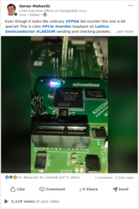
Also before ordering v002 I needed to check if SerDes part needed some change, the easiest way to check that was to use LiteX. I had some issues when I tried to build it https://github.com/enjoy-digital/liteiclink/issues/4 but I somehow managed to fix it directly inside of the generated files. And after loading the loopback sample in v001 board sample, the counter that counts received packets started to blink!
After SerDes confirmation it was time to order the v002 board!
Prices of 6 layer boards on a small scale are double then 4 layers – but that will not be a problem once we get a bigger order…
JLCPCB
5pcs. 4 Layer price €63.30 – ENIG – BLACK – 0.2/0.4mm
5pcs. 6 layer price €129.91 – ENIG – BLACK – 0.2/0.4mm
Stencil is €10.54 + it adds up €20 on shipping
Total JLCPCB costs are:
10 pcs. ULX4M-LS v002 €140.16
Stencil with frame €10.29
5 pcs. ULX4M HAT €6.96
Total including Tax and import fees: €257.47
It was kind of a miracle that 90pcs. of LFE5UM-85F-8BG381C parts where available on Mouser so I ordered them instantly.
Price of one UM-85F if 90 is ordered is $35.330
While waiting for parts I was cleaning schematics, and sorting everything that we need for production.
https://github.com/intergalaktik/ulx4m/blob/master/doc/schematics.pdf
Even for ULX3S we have noted that kitspace is really cool project sharing page and it helps a lot in part ordering and checking. It also has lots of other things integrated, like pcb ordering, gerber inspection, interactive BOM that is a really valuable tool for hand placement of components…
https://kitspace.org/boards/github.com/intergalaktik/ulx4m/
Hopefully I will get some time to record one video with complete ULX4M assembly.
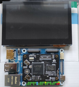
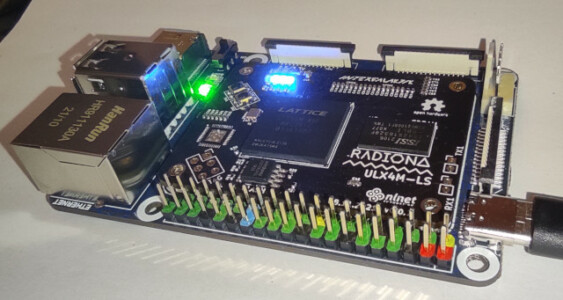
Everything arrived!
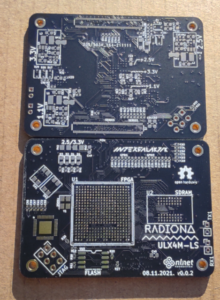
So hurry hurry, assembly time is here!
I got on board at 14h, and ULX4M was assembled a few hours later!
So first check if the connector will slip in the socket, and it does!
That was the biggest issue on v001, and only one was made, as it was really hard to fit the board to the socket.
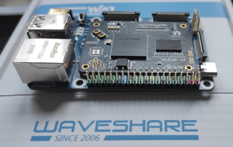
At some point I also ordered a Waveshare board and it also fit nicely!
I rewrote all the lpf files and checked a few samples to see if all that worked on v002 still works…
I also assembled one HAT as if that works it will be much easier to load samples.
On the first HAT I have placed ESP32 WROOM, but after a day of trying to get SD card sharing to work I decided to try with another HAT with ESP32 WROVER.
And instantly the SD CARD was available to ESP32!
So WROOM will probably need more work.
FTDI worked from the first try, so it is now possible to power board only from HAT USB and program it with fujprog, just like ULX3S.
On WROVER it is also possible to program board over WIFI, and WEBREPL and FTP are also working!
Bootloader was not so hard to adjust for ULX4M as smunaut, lawrie and emard already solved hard parts.
I have just adjusted the pinout, and needed to remove some LEDS and BUTTONS as they are not available on ULX4M.
I also changed the product, and manufacturer text in bootloader fw…

After all that I tried a fixed Litex SerDes sample, it needed some pin adjustments, but as Greg suggested I updated the fpga toolchain and no more direct fixes are needed. It is producing a working SerDes PCIe loopback sample.
Currently tested
LEDS – OK
BTNS – OK
HDMI0 – OK
HDMI1 – OK
SDRAM – OK
FLASH – OK
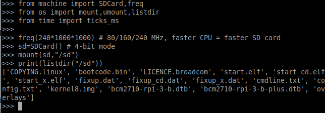
SD CARD – OK
SD CARD from HAT ESP32 – OK
Programming over HAT FTDI – OK
Programming over HAT ESP32 – OK – only WROVER
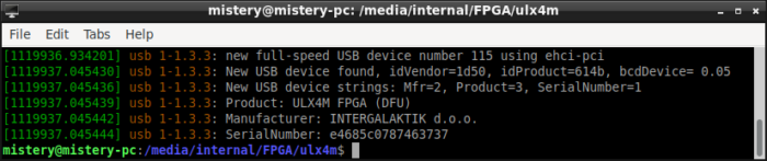
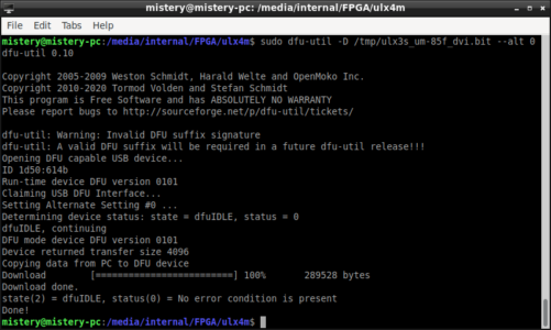
USB DFU bootloader – OK
PCIe serdes loopback – OK
Ethernet – Not routed – chip is not selected – SERDES still connected directly to coil
USB HUB – Connected but not tested – will need lawrie help as it is probably easiest to get it from SaxonSoc
SERDES RX TX antennas – EXPERIMENTAL! – not tested
CAM0 – EXPERIMENTAL! – All pins connected – not tested – be careful needs voltage level check
DISP0 – EXPERIMENTAL! – All pins connected – not tested – be careful needs voltage level check
CAM1 – EXPERIMENTAL! – All pins connected – not tested – voltage levels – has SERDES pins
DISP1 – EXPERIMENTAL! – All pins connected – not tested – voltage levels – has SERDES pins
I also checked with NLnet and they helped me with the license and license for ULX4M series will be
CERN-OHL-S v2 or later
https://github.com/intergalaktik/ulx4m/blob/master/LICENSE.md
Paula is still busy, but she thinks she can have a complete December just for blender!
And my next task will be to make a ULX4M-LD board – D stands for DDR in our case this will be DDR3.
In that time I hope other issues could be found if any and clear for ULX4M-LS v003…
And last news for now – at some point CrowdSupply accepted ULX4M Submission, and we have signed a Statement of Work! So expect the CrowdSupply ULX4M preview page soon!