Continuation of work ULX4M funded by NLnet
Milestone 2
•Start to work on first daughter board that will have selected connectors
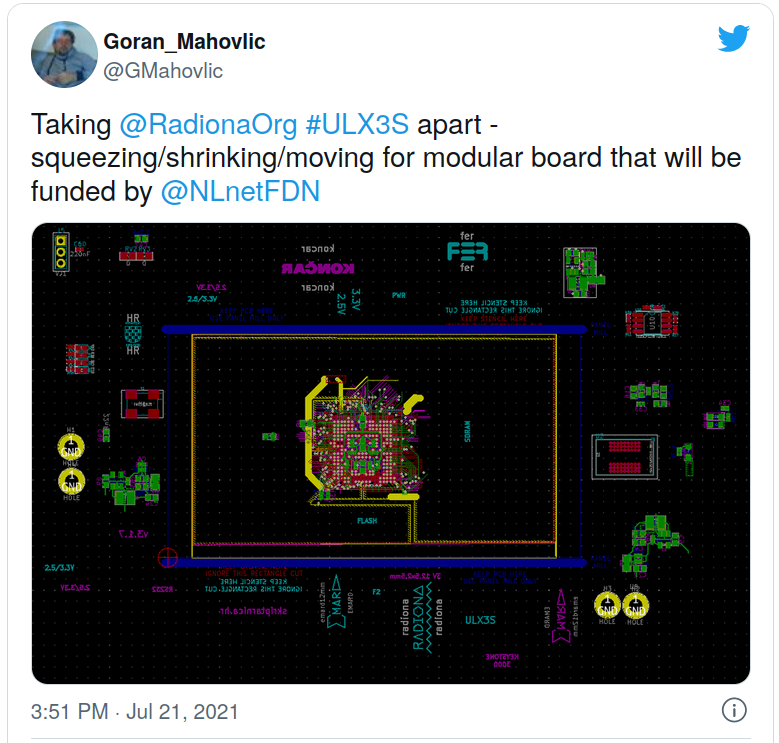
For start I first needed to completly dissasemble ULX3S.
I did that in a way of spliting into modules.
https://twitter.com/GMahovlic/status/1417844739303424000https://www.linkedin.com/posts/goran-mahovlic_ulx3s-innovation-activity-6823611763443933184-4n5O
Once I had everything separated I combined parts from same module.
After combining parts I checked what parts could be smaller, and changed them to smaller replacement.
Once I were satisfied with size I squeezed parts together, to have a little space, but still be nice and tight.
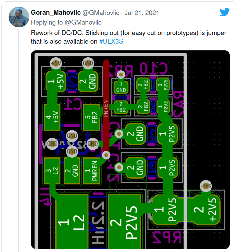
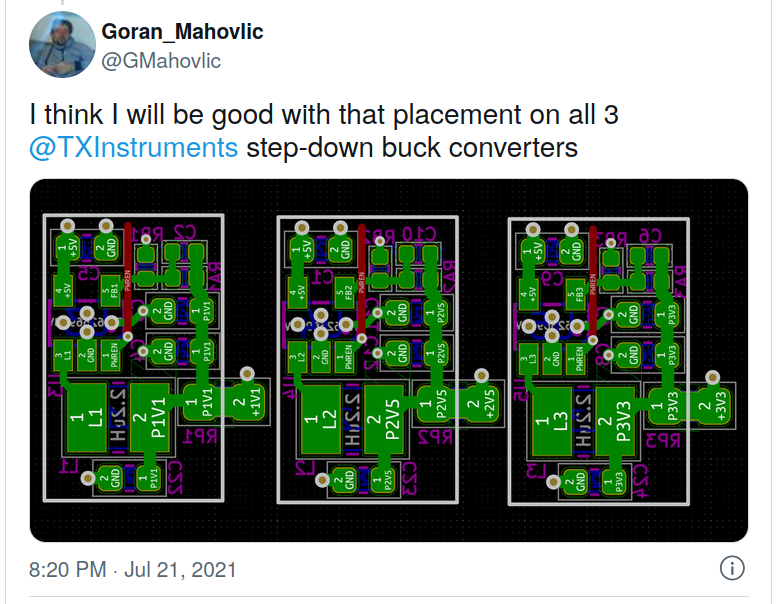
All 3 power supply modules are then sorted the same way. And rounded with lines.
Now PS units are looking like a puzzle…
•We will aim to have first version done simple as possible
While first plan was to just connect power supply and LEDS, chip shortages are teaching us to do more things at once, as parts are really hard to get. Just for a insite how hard, current wait time for lattice 85F is about 50 weeks.
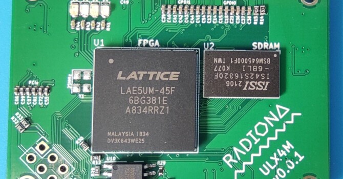
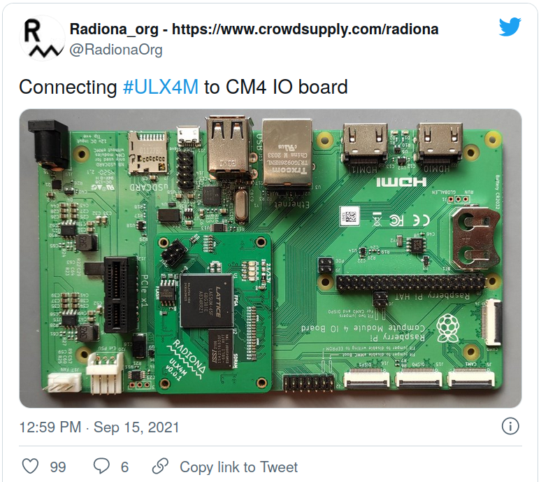
CM4 IO offeres a lots of periferals, and we also wanted to implement some new changes to ULX3S pinout.
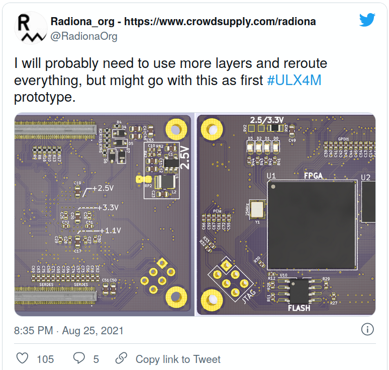
First thing we wanted was to change big TSOP-54 to BGA version. BGA versions are bit more expensive, but we will get more space.
Initial routing is done, but I will need to take more time in next version to make it more elegant.
Also changing to BGA gives us more confidence to experiment with DDR3 chip later. It would also be good if in next version I do length match, as in this version I did not do that. I did check length and it looked fine for the SDRAM.
Next thing we wanted was to connect at least one HDMI port to ECP5 true differential pins, as on ULX3S that is not the case. So we connected previously connected pins to HDMI1 port, and routed new true differential pins to HDMI0 port. True differential pins migh give us bit higher resolutions as we might be able to use DDR2 primitives.
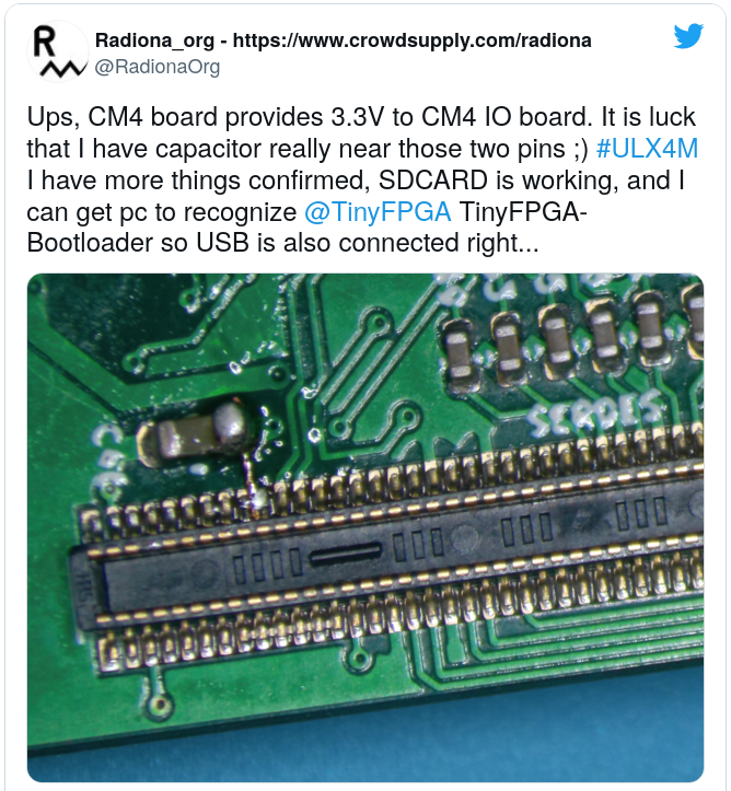
Next thing was to connect JTAG, and I decided to have it connected on board connector, and on pi GPIO pins so we can use it later from the HAT.After that USB lines are connected. If working whis would give us possibility to use USB bootloader, so users would not need to have external programmer or pi HAT.
CM4 IO USB pair is connected to MUX that is switching between micro USB connector and USB HUB PHY. So we can try to use both with just setting USB_ID pin HIGH/LOW – or it will be set high when we apply external power to micro USB connector(if connected to PC).
For v.0.0.1 I decided to stay on 4 layer board, as I could still fit most of the things, and it would be bit cheaper. Still I dit not expect perfection and we will still see if high speed signals would work.
With 4 layers it was not so easy to connect all I wanted, but I managed to connect most of it. Still not connected are most of the CM4 free GPIO pins that will be needed for pi HAT, and we still have two DSI connectors that are not connected, but once we test two that are connected we can switch to 6 layer board and route those two… 6 layer board will be needed, as it is already visible that ground plane under some pins (specialy high speed pins) is not perfect.
Connecting SDCARD was easy, but on next version we want those connections to be available on GPIO – so we can access them with ESP32 module that will be on the HAT, as on ULX3S ESP32 has proven to be quite usefull…
On ULX3S v3.1.6. we already have some serdespins out, but on ULX4M I managed to get all pins out, and connected them to capacitors. After that I routed one SERDES pair to top connector where PCIe pins are located on CM4 board. After that I did length match on those lines. Rest of SERDES pins are directly connected to ethernet coil. CM4 board has on board PHY that is providing Gb ethernet, but in this version we leved place for experiments with SERDES gatewares(we still do not know if something like that is possible or not, but worths a try).
For DSI interfaces I have just used one differential pair. I2C is also connected if we will need it to talk to camera or display…
•Order board
Board was ordered from JLCPCB and it arrived quickly
Quality was good as expected.
Stensil is also good, so we are good to go.
•Board assembly
I did board assembly in Intergalaktik. At some point I found 45SUM part available, so I ordered 5 pcs. to have on stock for SERDES experimenting versions.
When it comes to assembly Interactive HTML BOM plugin for KiCad is really amazing helping tool.
In HW assembly you are always missing at least one part even if you check multiple times.
When I was ordering parts for ULX4M I was sure I have some 0402 resitors, but at the time of assembly I could not find them. Luckaly 0603 could be placed on those connections it will just not look perfect.
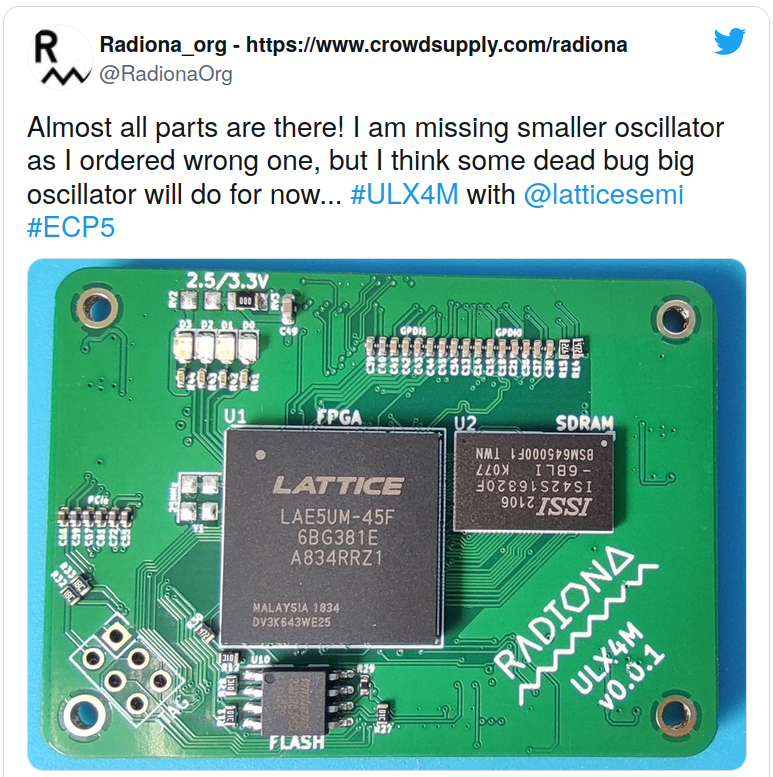
I discovered one more thing that osilators I ordered are bigger one for ULX3S and not smaller one I want, but I can do some dead bug oscilator on this version.
It turns out that I can flip dead bug oscilator on the right side, not perfect way to connect crutial part on the board, but we will see if it will work as expected…
We first need to apply paste, and we are using stencil for that.
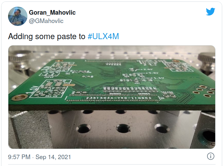
Bottom layer is done first, as you do not want to rebake FPGA if it is not needed. Also just bottom layer will give us info if powersupplys are working corectly.
Once paste is applyed I used Interactive HTML BOM to place parts and after placement I bake the board in my soldering owen. If someone is making this board at home I really recomend stencil, it would be realy easy to place other parts, but this connector is not easy to solder by hand. It is possible as I already did it on first prototype, but it is just much easyer with stencil.
So bottom side is done, and I connected just bottom assembled board to CM4 IO board to check connector and powersupply.
Power supplyes are showing good voltages on FPGA pins(3.3V, 2.5V, 1.1V).
•Board should slip into connector and blink some LED
Board does not slips into connector perfectly – it is missing probably 1mm. But I can make it fit into connector by slightly bending CM4 IO board. Once it sits there it stays at place. So in next version I need to move those connectors 1mm furder from each other.
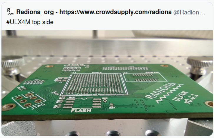
Top side was done quicker, it has less parts, most of them are just HDMI capacitors.
Placing ECP5 and SDRAM was not a problem.
•User opinions, considering/fulfilling whitelists, improvement of aesthetic and
functional design
We already have list of wishes. Maybe most important one is to add HAT to the CM4 IO.
Users that are using ULX3S really want possibility of using ESP32 as on ULX3S. So we will need to connect all pins to GPIO and connect SDCARD to those pins(and probably some more) to get it as on ULX3S.
On ULX3S lots of samples are already using ESP32 for example to load games with ESP32 OSD menu that is overlaying on top of FPGA picture…
•Have some pictures/animation of boards snapping together
in progress – waiting Paula
•Blog post
Milestone 3
•Fixing issues with first daughter board
We did first version with care, so lot of things are already working, but sill we will need more adjustments, but we will move those chages to milestone 4
•Starting to work on main board
Chip shortages, for now better to invest time in smaller boards.
HW companies and makers and probably others are currently facing really tough problem, and that is global chip shortages. I will not go into depth on that fiels as it is already writen multiple time, but I will just say that if we order lattice 85F chips today, soonest they can aperar is 50 weeks. And that is almost a year of wait. And still no one will garantie that the price will not rise in that time. one more problem is that you cannot just order chips and wait you need to pay them, then pay more if price rise, and that is currently quite an issue. Guided by that we invested double effort in first revision of modular board and make it compatible with already existing CM4 IO board. CM4 IO boards are everywhere, and there is also nice set of opensource boards, so instead doing one more CM4 IO board we will just use as much as we can from already available boards on the market.
•Add all ULX3S peripherals to the board, and leave placeholders for new peripheral
We have almost all and more periferals on CM4 IO board, plan is to reuse CM4 IO board, and add missing periferals to HAT board.
•User opinions, considering/fulfilling wishlist’s, improvement of aesthetic and
functional design
HAT board will need to have two USB connectors for connecting PS2 and USB keyboards, joysticks, mouse.
Would be great if we get simple VGA on the HAT, as VGA connector is always usefull to have.
I already wrote about ESP32 on HAT
As we do not have any buttons on ULX4M we need to place some of them to HAT board.
Few more LEDS are always usefull to have.
Maybe also simple ethernet PHY but we will first see if we can get onboard or PCIe version working.
POE would be super usefull
We could probably have one HDMI input
Would be cool if we do it respecting CM4 board, so that users with CM4 can also use HAT (or at least some parts of it)
DDR3 version of ULX4M is needed at some point
If SERDES version of ethernet is not possible we need to consider to have Gb ethernet chip on ULX4M board, but we also need to be carefull about that as adding just one chip can prolonge production by quite a long time.
•Blender animation
in progress – waiting Paula
•Main board assembly
•Write Verilog examples
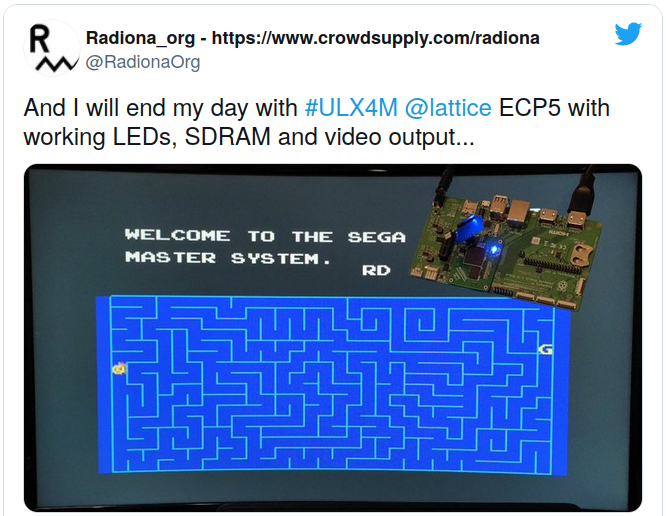
Tested – and we already have working Verilog examples:
LEDS – on board LEDS
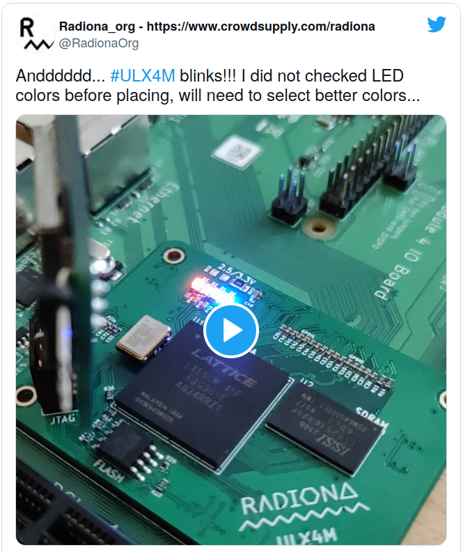
Blink led link: https://twitter.com/RadionaOrg/status/1438095898144301060
JTAG – on board connector
FLASH – on board flash
2 x HDMI output (one true differential – so we can try better resolutions)
USB bootloader – TinyBootloader – tnt will help us get DFU bootloader
64Mb SDRAM (tested with memtest)
SD CARD (tested with Next186)
Connected but not tested:
MIPI DSI display
MIPI DSI camera
PCIe
USB HUB chip
Ethernet (we have SERDES pins connected to connector)
•Test onboard peripherals
Pictures
•Twitter and LinkedIn
I am constantly trying to show or progress on twiter and LinkedIn
•CrowdSupply
I already contacted CrowdSupply and send all info needed to open ULX4M preview page. So we can check what is the interest on this board, and maybe get other valuable feedback. They will check, but they already love the board form factor.
•Blog post
Milestone 4.
•Adding high speed peripherals to the main board
PCIe connector is a great high speed periferal for experiments
•ULX4M repo cleanup
will do next – current repo is cloned from ULX3S, and all work in done on top of it, so it needs a good cleaning process so it bacame usefull to others…
From discord user Philpax has answer why having small board and carrier board is good idea
The board is a standard, which means there are multiple carrier boards
https://pipci.jeffgeerling.com/boards_cm
In the general case, same thing, just maybe not as many